
When it comes to diagnosing vehicle issues, one of the first steps is to use an On-Board Diagnostics (OBD) II scanner. This tool allows you to retrieve error codes and other information from your car’s computer system, helping pinpoint the source of any problems.
However, what happens when your OBD II scanner doesn’t communicate with your vehicle? In this guide, we will explore some potential causes and solutions for this issue.
There are a few reasons why your OBD II scanner may not be able to communicate with your vehicle. Here are some of the most common ones:
If the scan tool does not receive data from an OBD II vehicle
TEST 1: Connect the positive DMM lead to DLC pin 4 and the negative DMM lead to the negative battery terminal, using jumper wires if necessary. Do not connect to the body or chassis ground but to the battery terminal directly.
With the ignition on, the voltage drop across the ground terminal should be 0.1 Volts or less
TEST 2: Repeat for DLC pin 5
NOTE: An open circuit or high ground resistance means that the PCM will never enter diagnostic mode.
TEST 3: Voltage check on DLC pin 2. (does not apply to a Mazda MPV)
PCM transmits data on this pin
Connect the positive DMM lead to the class 2 Serial Data pin and the negative DMM lead to either pin 4 or pin 5 or a known good groun
TEST 1: Connect the positive lead of the Digital Multimeter (DMM) to DLC pin 4 and the negative lead to the negative terminal of the battery. If needed, you can use jumper wires. Ensure that you connect directly to the battery terminal and not the body or chassis ground.
With the ignition turned on, the voltage drop across the ground terminal should be 0.1 Volts or less.
Test 2: Repeat the procedure for DLC pin 5.
Note: If there is an open circuit or high ground resistance, the PCM will not enter diagnostic mode.
Test 3: Perform a voltage check on DLC pin 2 (not applicable to a Mazda MPV).
The PCM transmits data through this pin.
Connect the positive lead of the DMM to the class 2 Serial Data pin, and the negative lead to either pin 4, pin 5, or a known good ground.
With the ignition on, the voltage on the class 2 serial data pin should be 5V or fluctuate between 3.5V and 5.0V. If the circuit is open, the PCM will be unable to transmit data to the scan tool.
With the Ignition on, the voltage on class 2 serial data pin should be 5V or fluctuating between 3.5V and 5.0V, If open, PCM cannot transmit data to the scan tool.
When it comes to diagnosing vehicle issues, one of the first steps is to use an On-Board Diagnostics (OBD) II scanner. This tool allows you to retrieve error codes and other information from your car’s computer system, helping pinpoint the source of any problems.
However, what happens when your OBD II scanner doesn’t communicate with your vehicle? In this guide, we will explore some potential causes and solutions for this issue.
There are a few reasons why your OBD II scanner may not be able to communicate with your vehicle. Here are some of the most common ones:
TEST 1: Connect the positive lead of the Digital Multimeter (DMM) to DLC pin 4 and the negative lead to the negative terminal of the battery. If needed, you can use jumper wires. Ensure that you connect directly to the battery terminal and not the body or chassis ground.
With the ignition turned on, the voltage drop across the ground terminal should be 0.1 Volts or less.
Test 2: Repeat the procedure for DLC pin 5.
Note: If there is an open circuit or high ground resistance, the PCM will not enter diagnostic mode.
Test 3: Perform a voltage check on DLC pin 2 (not applicable to a Mazda MPV).
The PCM transmits data through this pin.
Connect the positive lead of the DMM to the class 2 Serial Data pin, and the negative lead to either pin 4, pin 5, or a known good ground.
With the ignition on, the voltage on the class 2 serial data pin should be 5V or fluctuate between 3.5V and 5.0V. If the circuit is open, the PCM will be unable to transmit data to the scan tool.
TEST 4:
Connect the positive lead of the digital multimeter (DMM) to the positive terminal of the DLC battery. Connect the negative lead of the DMM to the ground terminal of the battery. The DMM should display the battery voltage. This test is performed to check the voltage supply to the ECM, as a lack of power could be due to a blown lighter fuse.
TEST 5:
Connect the positive lead of the DMM to either of the DLC bias terminals. Connect the negative lead of the DMM to the ground terminal. With the ignition key turned ON and no bus activity, the BUS + reading should be 0V and the BUS reading should be 5V. With the ignition key turned ON and bus activity present, the voltage reading should vary from 0 to 5V, depending on the level of bus activity.
ADDITIONAL NOTES PCM receives battery voltage (B+) through a fuse or fusible link. Check for an open circuit. An open ground or power (B+) circuit on a fuel-injected engine removes power from the ECM and prevents the engine from starting.
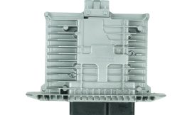
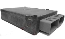
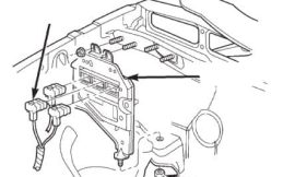
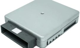
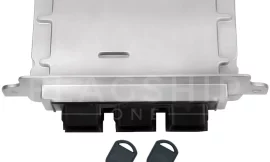
ADDITIONAL INFORMATION: Old PCM is fried, see the attached picture when attempts are made to communicate after fixing the wiring problem.
The new PCM is functioning properly. However, it’s worth checking the fuse box (Power Panel) as it could potentially be the cause of the PCM’s power supply and communication issues.
TEST 4:
Connect positive DMM lead to DLC Battery + terminal Connect negative DMM lead to battery ground terminal
It should read battery voltage
This tests the ECM Voltage supply as no power may be caused by a blown lighter fuse
TEST 5: Connect positive DMM lead to either DLC bias terminals Connect negative DMM lead to the ground terminal
With the ignition key ON and no bus activity, BUS + should read 0V BUS should read 5V
With the ignition key ON and bus activity, the voltage should vary from 0 to 5V depending on the amount of bus activity!
ADDITIONAL NOTES PCM receives battery voltage (B+) through a fuse or fusible link. Check for an open circuit. An open ground or power (B+) circuit on a fuel-injected engine removes power from the ECM and prevents the engine from starting.
ADDITIONAL INFORMATION: Old PCM is fried, see the attached picture when attempts are made to communicate after fixing the wiring problem.
The new PCM works fine.
Check the fuse box (Power Panel), it might be the reason why PCM isn’t able to receive power as well as communicate.
The world's top supplier of programmed OEM (Original Equipment Manufacturer) Powertrain Control Modules (PCM), Engine Control Modules (ECM), Injection Control Modules (IDM), Body Control Modules (BCM), Transmission Control Modules (TCM), Engine Control Units and all other car control units. With over a decade in the business, we are the most reliable source when it comes to programming services for replacement engine control modules.
February 6, 2020
April 12, 2019
June 9, 2016
August 14, 2019

August 19, 2019
September 29, 2020

August 1, 2018
August 5, 2020

August 6, 2018
April 9, 2020
June 4, 2018
April 7, 2019

March 29, 2022
November 23, 2021
TFor 2008 FX35 Infinit 3,5L
Test 3, which terminal is for serial data?
Test 5, which terminal is bias terminal?
Thanks,
Bill
TEST 5: Connect positive DMM lead to either bias pin 2 or 10 and connect negative lead to the ground terminal.
*Ignition ON/NBA** BUS+(2) should read 0V BUS (10) should read 5V
*With the ignition key ON and bus activity (BA), the voltage should vary from 0 to 5V depending on the amount of bus activity!
**No Bus Activity! all Acessories Off